PDP-11: Programming like it's 1975

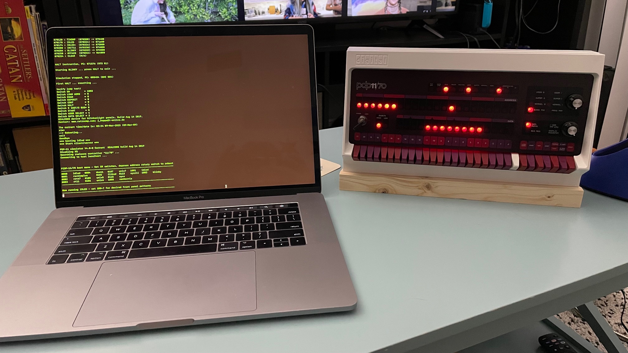
In April of 2023 I acquired the popular PiDP-11 from Oscar here . It is currently my favorite machine to program for. Here's a picture of me running a sample program for the first time.

Card image cap

Programming the Hard Way

I wanted to immediately start programming, so I started by entering sample programs I found online into memory using the switches located on the front of the unit. This is not an ideal long term solution, but it has taught me a lot so far.

To start messing with memory after boot up, do the following:

  • 1. Boot into the sample blinking lights program
  • 2. Move the "ENABLE/HALT" switch down to halt the current program
  • 3. Depress the "LOAD ADRS" switch to load address 0000008
  • 4. Start entering opcodes and data

This is the short and simple version of events. I will explain more as we go.

1. Input Assembler

To draw an object to the screen, information is required as to where and how an object should be drawn. The basic geometric data required for defining a graphical primitive are vertices and indices. DirectX 12 requires triangles and quads to define objects drawn to the screen, and a primitive topology must be defined to DirectX 12 so the GPU can properly interpret the data provided to it.

2. Vertex Shader

A graphics shader is defined in a HLSL (high level shader language). The file will be compiled into two parts: a vertex shader and a pixel shader. The Vertex Shader stage is when the code written in the vertex shader is run on the GPU. A vertex shader is essentially a function that takes a vertex, does a bunch of operations on it, and then outputs the new vertex. Any per-vertex work is done here, like transforming a model or applying some lighting effects.

3. Rasterizer

Frank Luna's "Intro to 3D Programming" book simply states that it’s job is to “compute pixel colors from the projected 3D triangles.” This is true, but the practical benefits are much more interesting. The rasterizer can interpolate vertex attributes between vertices, such as blending colors across a cube. It is also where backface culling computed. Backface culling is when any triangle of an object is facing away from the camera, these rear facing triangles are not rendered, which is faster than drawing them.

4. Pixel Shader

A pixel shader will take the aforementioned vertex shader’s output and use it as input. This output is then applied to any pixels that have not been eliminated by previous stages of the pipeline. This is also where effects that require per-pixel computation are done, like reflections and shadowing.

5. Output Merger

This is the last stage before the data computed so far is written to the back buffer to be displayed. Depth and stencil test are done here, eliminating even more unnecessary rendering, such as when an object is hidden behind another object.

Resources

DirectX 12 has different resources that allow the user to define what happens in this pipeline. A resource is essentially a chunk of memory that the CPU and GPU can access. Resources are described using descriptors, an indirection that tells the GPU what is in the resource so it can act accordingly. Much of the DirectX 12 code I have written handles resources and descriptions for the pipeline, root signatures, textures, constant buffers, and more.

Another important part of the DirectX12 model is the Command Queue, Command Allocators, and Command Lists. The Command Queue is important; it will be where all of the Command Lists are executed. Command Allocators are the memory where Command Lists live. It is recommended by Nvidia (Nvidia Developer Site) to use multiple Command Allocators and Command Lists when writing multi-threaded applications, and generating one allocator and list per frame buffer, multiplied by the number of threads, plus an extra set for bundles. All Command Lists, no matter what thread they live on, must make their way into the Command Queue at some point.

My Graphics Engine Implementation

DX_Framework

My graphics engine is structured in a similar fashion to the Azul engine that we have been using at DePaul. My class for controlling much of the DirectX 12 code is called “DX_Framework”. A large chunk of DirectX 12 code used for starting up and shutting down the system lives here. This is also where my code for Win32 application operations also lives. I have plans to continue to work on abstracting the Win32 code out of this framework into it’s own class. I also have to mention that I opted for a Triple Frame Buffering system for my game loop. This allows me to write to other render frames before the current frame is done rendering. This has various effects on the setup I describe here, so it is important to keep in mind. Here is the order and descriptions of the steps I take to setup the DirectX 12 environment in engine. DirectX 12 Engine Initialization:

  • 1. Device Creation
  • 2. Command Queue Creation
  • 3. Swap Chain Description and Creation
  • 4. Render Target View Heap Creation
  • 5. Command Allocator and Command List Creation
  • 6. Create Fences
  • 7. Depth & Stencil Buffer View Creation
  • 8. Viewport and Scissor Rectangle Settings

1. Device Creation

This stage is simple. I poll the system to find a DirectX 12 compatible hardware GPU adapter and get a handle to it, which is known as a Device. The Device is used to get and set various things to and from the GPU adapter.

2. Command Queue Creation

This is where I create the Command Queue. There is nothing fancy here, because there is only one Command Queue for the whole application.

3. Swap Chain Description and Creation

This is where things start to get more complicated. The swap chain need to know how many frame buffers I plan on using so it can create them. An application needs at least two, but I have opted for three.

4. Render Target View Heap Creation

Render Target Views are used to bind resources to pipeline stages. Here I create a Render target View for each frame buffer created when I setup the Swap Chain.

5. Command Allocator and Command List Creation

This is where I create the Command Allocators and Command Lists I will be using in my engine. I am not generating any of my own threads, and I am not using bundles, so I only create an allocator and list for each frame buffer. This is how I can write to the next buffer while the previous buffer is still rendering to the screen!

6. Fence Creation

Even though I am not using multi-threading on the CPU side of the system, I still need to be able to coordinate my operations with the GPU. At a high level, this can be very similar to writing a standard multi-threaded program with two threads; synchronization methods must be used or bad things tend to happen. Fences are used to make sure that the CPU and GPU do not fall out of sync with each other.

7. Depth & Stencil Buffer View Creation

The Depth & Stencil Buffer View allows me to do things like determine which objects should be drawn when one is overlapping another. There is only one of these that needs to be generated.

8. Viewport and Scissor Rectangles

These are settings that tell DirectX 12 what parts of the application window to render to. These are set to the default values of the window’s width and height for my purposes.